Utilizing Class I Div. 2 Circuit Breakers in Liquid Natural Gas Applications
An increase in the demand for energy worldwide has driven the search for alternative primary sources of energy, even to the most remote locations of the globe. Natural gas, one of the leading alternative energy choices for fueling industries today, is considered the cleanest burning fossil fuel with minimal environmental impact.
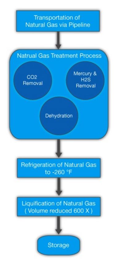
The most popular way to move gas from source to end user is through pipelines, based on its relatively low energy content per unit of volume. However as transportation distances increase, so does the cost of the pipeline – making it difficult to transport natural gas from the wellhead to customers economically. To optimize the transportation of natural gas, a liquefaction process is used. This process converts natural gas into liquefied natural gas (LNG) by refrigerating natural gas to -260°F (-162.22°C), resulting in the reduction in the volume by approximately 600 times its gaseous form.
Liquid Natural Gas Treatment Process:
The chemical make-up of natural gas includes complex contaminate such as CO2, H2S, CO and other acidic gases which can hinder the liquefaction process. For example, CO2 can freeze on the exchanger surfaces, plugging lines and reducing plant efficiency. Therefore there is a need to extract the CO2 before the liquefaction process begins. This is needed not only to overcome the process bottle necks, but also to meet LNG product specifications, prevent corrosion of process equipment and the plant environment.
There are many gas treating processes available for the removal of CO2 from natural gas. These processes include: chemical solvents, physical solvent, adsorption processes, hybrid solvents, and physical separation. These chemical and physical solvents or a combination of these have been used extensively in existing LNG facilities. There is one common factor to all of these gas treating processes. They all require a sophisticated Automation/Process Control system. Most of these systems are configured with a high level, redundant DCS or PLC controller, utilizing industrial networks to connect the 100’s of inputs and outputs, both analog and digitally based for the instrumentation and valves used to control and monitor the entire process. These applications are also considered to be in Hazardous locations for electrical control equipment and instrumentation, mainly because of the possibility of explosion during liquefaction and re-gasification processes and electrical arcing components incorporated into the control cabinet. This environment is known as a Class I, Division 2, Hazardous location.
Automation Control Systems in Hazardous Environments:
Several options are available to deploy an automation control system in a hazardous environment. In the past, NEMA 7 Explosion Proof Enclosures were predominately used to install the electrical controls. These enclosures are designed to prevent any arcing or flame from a component failure inside the enclosure to the outside volatile process area. Today, a NEMA 4/4X industrial enclosure is commonly utilized with an Air Purge System. These systems exchange the air from inside the enclosure with fresh air processed through the purge system - minimizing high concentration levels of hazardous gases in the enclosure which could cause an explosion with an arcing component, such as a electrical relays, switches, fuses, circuit breakers, etc. As an replacement to both of these options, E-T-A offers a line of solid state electronic circuit breakers for Class I, Division 2, Hazardous location applications. This new solid state technology is an alternative for protecting 24 VDC field devices in a hazardous location because as long as all the components installed in an electrical control enclosure have a Class I, Div. 2, approval, the NEMA 7 enclosure and/or Purge System are no longer needed to meet most application specifications.
Real Life Example - Salof Companies:
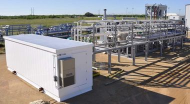
In recent months E-T-A, along with Salof Companies, a leading Liquid CO2 and LNG system supplier, successfully deployed its new solid state electronic product on an LNG Pre-Treatment application.
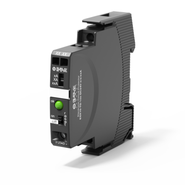
Several factors lead the Salof Control Engineering team to implement this new technology into its design including, the need to meet specifications to protect all field devices with overload and short circuit protection, as well as provide a means for individual disconnection of each field load in a Class I, Division 2, hazardous location. Alan Dingeldein, EPM/Control Engineer on the project, discovered this new solid state technology through an electronic newsletter sent by Weidmuller. By integrating E-T-A’s solid state device, Salof benefitted from better protection for field devices than any other technology available for 24VDC switch mode power supplies. The E-T-A product is designed to detect both an overload and short circuit condition within 200 ms of the over-current event. Because this component has a current-limit function it will supply no more than 1.3 times rated current of the circuit breaker at any time during the fault condition, then after 3 seconds completely disconnects the current from the switch mode power supply to the load. In the event of an overload or short circuit, the device allows for individual disconnection between the power source and the load via a power switch on the face of the product. Other models have a Remote Reset option allowing a PLC/DCS control output to disable or disconnect the current flow to the field load preventing the power supply from being compromised by a single point of failure.
ESX10-T Electronic Circuit Breaker:
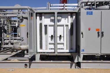
This product carries a UL 1604, Class I, Div. 2 (CID2) approval, which allows it to be used in this application with a CID2 switch mode power supply, I/O modules, terminal blocks, and industrial switches. Because all of the components were CID2 approved, a purge system was not required for this project. The system was deployed in a standard NEMA 4X, double door enclosure. This saved significant time and cost throughout the entire project cycle, from the design phase, to electrical checkout, to customer acceptance testing, to final site installation. In the long term, the end user will not have to maintain a purge system and the associated output alarms to the Process Control System.
The basic device is designed with a Red/Green LED mounted on the face which allows for immediate visual indication of the circuit breakers output status to simplify troubleshooting 100’s of I/O field devices. More advanced models have an active high or low output single that can be used to integrate with the PLC/DCS control system or enclosure door mounted pilot light. This feature increases production for the end user by locating the root cause of failure of the field devices very quickly, and allows them to get back on line, producing product once again. As an additional benefit, the status indication on the device reduced the amount of time necessary to identify faulty instruments in the control system during to initial electrical start-up.
Outcome:
The integration of this alternative approach enabled Salof to meet its project goals by fulfilling the required Class I, Division 2 load protection and individual disconnection all of the field instruments and valve devices. The use of the E-T-A product eliminated the need for a purge system which reduced the overall equipment and labor cost of the project. This lead to a reduction in the amount of time needed to perform the initial electrical startup of the control system based on the LED status indication of the solid state electronic circuit breaker.


